There are two types of motion sensors: active motion sensors and passive motion sensors.
A motion sensor (or motion detector) is an electronic device that is designed to detect and measure movement. Motion sensors are used primarily in home and business security systems, but they can also be found in phones, paper towel dispensers, game consoles, and virtual reality systems. Unlike many other types of sensors (which can be handheld and isolated), motion sensors are typically embedded systems with three major components: a sensorunit, an embedded computer, and hardware (or the mechanical component). These three parts vary in size and configuration, as motion sensors can be customized to perform highly specific functions. For example, motion sensors can be used to activate floodlights, trigger audible alarms, activate switches, and even alert the police.
There are two types of motion sensors: active motion sensors and passive motion sensors. Active sensors have both a transmitter and a receiver. This type of sensor detects motion by measuring changes in the amount of sound or radiation reflecting back into the receiver. When an object interrupts or alters the sensor’s field, an electric pulse is sent to the embedded computer, which in turn interacts with the mechanical component. The most common type of active motion detector uses ultrasonic sensor technology; these motion sensors emit sound waves to detect the presence of objects. There are also microwave sensors (which emit microwave radiation), and tomographic sensors (which transmit and receive radio wave) .
Unlike an active motion sensor, a passive motion sensor does not have a transmitter. Instead of measuring a constant reflection, the sensor detects motion based on a perceived increase of radiation in its environment. The most widely used type of passive motion sensor in home security systems is the passive infrared (PIR) sensor. The PIR sensor is designed to detect the infrared radiation emitted naturally from the human body. The receiver is contained in a filter that only allows infrared to pass through it. When a person walks into the PIR sensor’s field of detection, the difference in radiation creates a positive charge within the receiver; this perceived change causes the sensing unit to send electrical data to the embedded computer and hardware component.
As the manufacturing world becomes more integrated with automated technology, it’s important to understand how this technology can help you. Industrial automation can make the lives of those working on the production floor easier and help increase a company’s productivity. One type of those devices helping workers is known as photoelectric sensors.
Photoelectric sensors come in many different forms and can be used in a variety of industries to accomplish a diverse list of tasks. In order to know which sensor is best, below is a breakdown of what is a photoelectric sensor?
What is a Photoelectric Sensor?
A photoelectric sensor is a device that detects a difference in the light level received from the light source. The sensor is made up of a light source, an amplifier, signal converter, and an output.
Three Types of Photoelectric Sensors
There are three major types of photoelectric sensors: thru-beam, retroreflective, and diffused. Each sensor has its own strengths and can be used in a variety of ways.
Thru-Beam
In thru-beam sensing, also known as opposed mode, two separate devices are used to make or break a beam. One sensor houses the light emitter while the other houses the receiver. A thru-beam sensor detects objects when an object interrupts the light beam between the two sensors.
Thru-beam sensors can be used to:
Detect very small objects.
Detect the fill levels inside containers.
Detect spliced or overlapped materials.
Detect the precise location of a specific object.
Detect the contents of a container.
Detect opaque objects.
The advantages of using a thru-beam sensor are that it’s the most accurate type of sensor and has the longest sensing range of the three. Thru-beam sensors are also the best choice when using them in a dirty environment. It’s important to keep in mind that there will be at least two separate parts which need to be installed in order to make this device work correctly.
Retroreflective
In retroreflective sensing, both the light source and the receiving device are found in the same housing. The sensor works in tandem with a reflector. The light emitted from the sensor is aimed at the reflector, which is then sent back to the light receiving element. The sensor detects the presence of an object when the light path is interrupted.
In addition to retroreflective sensing, there is polarized retroreflective sensing. Polarized retroreflective sensing features a polarized optical block which reduces the response to “hot spot” glare from a shiny surface of the detected object.
Retroreflective sensors can be used to:
Detect large objects.
Detect objects moving at high speeds.
Detect reflective tape at high speeds.
Sense a transparent (clear) glass or plastic product.
Retroreflective is a more affordable and only slightly less accurate option than thru-beam sensors. When working with clear or transparent products, retroreflective sensors are the best option. Another advantage is that retroreflective sensors only need to be wired on one side while thru-beam sensors require wiring on both sides of the device.
Diffused
In optical proximity sensing, also known as diffuse, the light source and the receiver are housed in the same device. Diffused sensors detect objects when the light beam, emitted towards the target, is reflected back to the sensor by the target. What makes diffused sensors a great automation option is that they are more compact than typical units, as all components are in a single housing.
Diffused sensors can be used to:
Detect multiple objects on a common conveyor system.
Detect translucent objects.
Detect the fill level inside containers.
Detect the presence of parts, boxes, and web materials.
Detect specific identifying features to determine an object’s orientation.
Detect unwanted conditions for product inspection tasks.
Diffused sensors are the easiest to install because everything is included in a single device and is a cost-effective sensing solution. The drawbacks to diffused sensors are they are less accurate when used in position detecting than thru-beam and retroreflective sensors and they are not as effective on translucent objects. In addition, these sensors can be the most affected by color, texture, the angle of incidents, target characteristics, and dirty environments.
Position sensors are devices that can detect the movement of an object or determine its relative position measured from an established reference point. These types of sensors can also be used to detect the presence of an object or its absence.
There are several sensor types that serve similar purposes to position sensors and which are worthy of mentioning. Motion sensors detect the movement of an object and can be used to trigger action (such as illuminating a floodlight or activating a security camera). Proximity sensors as well can detect that an object has come within range of the sensor. Both sensors, therefore, might be considered as a specialized form of position sensors. More about these sensors may be found in our related guidesabout proximity sensors and about . One distinction with position sensors is that they are for the most part concerned with not only the detection of an object but also with the recording of its position and therefore involve the use of a feedback signal that contains positional information.
This article will present information on the different types of position sensors, how they work, how they are used, and the key specifications associated with this class of sensor. To learn more about other types of sensors, see our related guides that cover the different types of sensors and their uses or the different types of Internet of Things (IoT) sensors . For purposes of this article, the terms position sensor and position detector are presumed to be synonymous.
Types of Position Sensors
The overall intent of a position sensor is to detect an object and relay its position through the generation of a signal that that provides positional feedback. This feedback can then be used to control automated responses in a process, sound alarms, or trigger other activity as dictated by the specific application. Generally speaking, position sensors may be divided into three broad classes that includelinear position sensors, rotary position sensors, and angular position sensors . There are several specific technologies that can be employed to achieve this result, and the different types of position sensors reflect these underlying technologies.
The primary types of position sensors include the following:
Potentiometric Position Sensors (resistance-based)
Inductive Position Sensors
Eddy Current-Based Position Sensors
Capacitive Position Sensors
Magnetostrictive Position Sensors
Hall Effect-Based Magnetic Position Sensors
Fiber-Optic Position Sensors
Optical Position Sensors
Ultrasonic Position Sensors
Potentiometric Position Sensors
Potentiometric Position Sensors are resistance-based sensors that use a resistive track with a wiper that is attached to the object whose position is being monitored. Movement of the object causes the wiper to change its position along the resistance track and therefore alter the measured resistance value between the wiper position and the end of the track. In this manner, the measured resistance can be used as an indicator of the object’s position. This is accomplished by using a voltage divider where a fixed voltage is applied across the ends of the resistance track, and the measured voltage from the wiper position to one end of the track yields a value that is proportional to the wiper position. This approach works for both linear displacements and rotary displacements.
Potentiometer styles used for potentiometric position sensors include wirewound, cermet, or plastic (polymer) film. These types of position sensors offer relatively low cost, but also suffer from low accuracy and repeatability. In addition, the size limitation of the device by design constrains the range over which the positional change can be measured.
Inductive Position Sensors
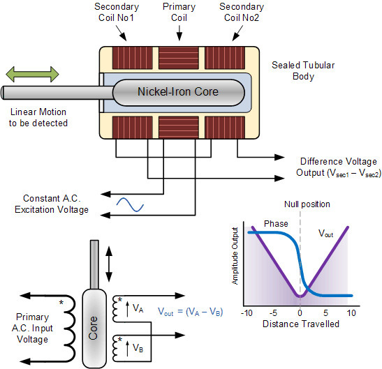
Inductive position sensors detect the position of an object by changes in the characteristics of a magnetic field that is induced in coils of the sensor. One type is called an LVDT, or Linear Variable Differential Transformer. In an LVDT position sensor, three separate coils are wound on a hollow tube. One of these is a primary coil, and the other two are secondary coils. They are wired electrically in series, but the phase relationship of the secondary coils is 180o out of phase with respect to the primary coils. A ferromagnetic core or armature is placed inside of the hollow tube, and the armature is connected to the object whose position is being measured. An excitation voltage signal is applied to the primary coil which induces an EMF in the secondary coils of the LVDT. By measuring the voltage difference between the two secondary coils, the relative position of the armature (and this the object to which it is attached) can be determined. When the armature is exactly centered in the tube, the EMFs cancel out resulting in no voltage output. But as the armature moves off the null position, the voltage and its polarity changes. Therefore, the amplitude of the voltage along with its phase angle serve to provide information that reflects not only the amount of movement away from the center (null) position but also its direction. Figure 1 below illustrates the operation of a Linear Variable Differential Transformer, showing the translation of the voltage measurement into an indication of position.
Figure 1 - Operation of an LVDT Inductive Position Sensor
These types of position sensors provide good accuracy, resolution, have high sensitivity, and offer good linearity across the sensing range. They are also frictionless and can be sealed for use in conditions where there might be exposure to the elements.
While LVDTs function to track linear movement, an equivalent device called an RVDT (for Rotary Voltage Differential Transformer) can provide tracking of the rotational position of an object. The RVDT functions identically to the LVDT and varies only in the specifics of their construction.
Eddy Current-Based Position Sensors
Eddy currents are induced currents that occur in a conductive material that is in the presence of a changing magnetic field and are a result of Faraday’s law of induction. These currents flow in closed loops and in turn, result in the generation of a secondary magnetic field.
If a coil is energized by ay an alternating current to generate a primary magnetic field, the presence of a conductive material brought near the coil can be sensed due to the interaction of the secondary field generated by the Eddy currents, which impacts the impedance of the coil. So, the change in the coil impedance can be used to establish the distance of an object from the coil.
Eddy current position sensors work with electrically conductive objects. Most Eddy current sensors function as proximity sensors, designed to establish that an object has approached the sensor location. They are limited as position sensors because they are omnidirectional, meaning that they can establish the relative distance of the object from the sensor but not the direction of the object relative to the sensor.
Capacitive Position Sensors
Capacitive position sensors rely on detecting a change in capacitance value to establish the position of the object being measured. Capacitors consist of two plates separated from each other with a dielectric material between the plates. There are two general methods that are used to detect the position of an object using a capacitive position sensor:
By altering the dielectric constant of the capacitor
By altering the overlapping area of the capacitor plates
In the first case, the object being measured is attached to the dielectric material, whose position relative to the capacitor plates changes as the object moves. As the dielectric material is shifted, the effective dielectric constant of the capacitor changes being the resultant of a partial area of dielectric material and the balance being the dielectric constant of air. This approach provides a linear variation in the capacitance value with respect to the object’s relative position.
In the second case, instead of attaching the object to the dielectric material, it is connected to one of the capacitor plates. Therefore, as the object moves its position, the overlapping area of the capacitor plates changes, which again changes the capacitance value.
The principle of varying capacitance to measure an object’s position can be applied to motion in both linear and angular directions.
Magnetostrictive Position Sensors
Ferromagnetic materials such as iron, nickel, and cobalt exhibit a property known as magnetorestriction, which means that the material will change its size or shape when in the presence of an applied magnetic field. A magnetorestrictive position sensor takes advantage of this principle to establish an object’s position.
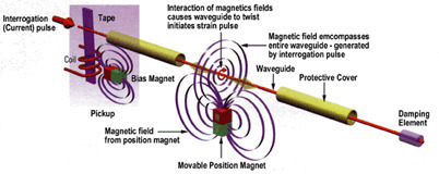
A moveable position magnet is attached to the object being measured. A waveguide, which consists of a wire through which a current pulse is transmitted, is connected to a sensor that is located at the end of the waveguide. The position magnet generates an axial magnetic field, one whose field lines are coplanar with respect to the magnetorestrictive wire and waveguide. When a current pulse is sent down the waveguide, a magnetic field is created in the wire that interacts with the axial magnetic field of the permanent magnet (position magnet). The result of the field interaction is a twisting that is known as the Wiedemann effect. This twisting causes a strain in the wire which generates a sonic pulse that travels along the waveguide and is detected by the sensor at the end of the waveguide. By measuring the elapsed time between the initiation of the current pulse and the detection of the sonic pulse, the magnetorestrictive position sensor can establish the relative location of the position magnet.
Because the sonic wave will travel from the location where the position magnet is located in two directions (both towards the pickup sensor and away from it), a dampening device is located at the opposite end of the waveguide to absorb the pulse traveling away from the sensor so that its does not cause an interfering signal to be reflected back towards the pickup sensor. Figure 2 below provides an illustration of the operating principle for a magnetorestrictive position sensor.
Figure 2 - Magnetoresistive position sensor operation.
By their nature, magnetorestrictive position sensors are used to detect linear position. They can be equipped with multiple position magnets to provide positional information on multiple components along the same axis. They are non-contact sensors and since the waveguide is typically housed in a stainless steel or aluminum tube, these sensors can be used in applications where they can be a potential for contamination. In addition, magnetorestrictive position sensors can function even if there is a barrier between the waveguide and the position magnet provided that the barrier is made of a non-magnetic material.
The sensors are available with a variety of outputs, including DC voltage, current, PWM signal, and start-stop digital pulses.
Hall Effect-Based Magnetic Position Sensors
The Hall effect states that when a thin flat electrical conductor has a current flowing through it and is placed in a magnetic field, the magnetic field impacts the charge carriers, forcing them to accumulate on one side of the conductor relative to the other, to balance the interference of the magnetic field. This unequal distribution of electrical charges results in the creation of a potential difference between the two sides of the conductor, known as a Hall voltage. This electrical potential occurs in a direction that is transverse to the direction of the flow of the electrical current and to the direction of the magnetic field. If the current in the conductor is held to a constant value, the magnitude of the Hall voltage will directly reflect the strength of the magnetic field.
In a Hall effect position sensor, the object being measured for its position is connected to a magnet that is housed in the sensor shaft. As the object moves, the position of the magnet changes relative to the Hall element in the sensor. This movement of position then changes the strength of the magnetic field that is applied to the Hall element which in turn gets reflected as a change to the measured Hall voltage. In this manner, the measured Hall voltage becomes an indicator of the object’s position.
Fiber-Optic Position Sensors
Fiber-optic position sensors use an optical fiber with a set of photodetectors located at each end of the fiber. A light source is attached to the object whose motion is being observed. Light energy that is directed into the fluorescent fiber at the position of the object gets reflected in the fiber and is sent to either end of the fiber where it is detected by the photodetectors. The logarithm of the ratio of the measured optical power as observed at the two photodetectors will be a linear function of the distance of the object from the end of the fiber, and therefore this value can be used to provide positional information on the object.
Optical Position Sensors
Optical position sensors operate using one of two principles. In the first type, light is transmitted from an emitter and sent over to a receiver at the other end of the sensor. In the second type, the emitted light signal is reflected from the object being monitored returned towards the light source. A change in the light characteristics (e.g. wavelength, intensity, phase, polarization) is used to establish information about the object’s position. These types of sensors fall into three categories:
Transmissive optical encoders
Reflective optical encoders
Interferential optical encoders
Encoder-based optical position sensors are available for both linear and rotational movement.
Ultrasonic Position Sensors
Similar to optical position sensors, ultrasonic position sensors emit a high-frequency sound wave generated typically from a piezoelectric crystal transducer. The ultrasonic waves generated from the transducer are reflected from the object being measured, or target, back to the transducer where an output signal is generated. Ultrasonic sensors can function to perform as proximity sensors, where they report on an object being within a specified range of the sensor, or as a position sensor which provides ranging information. The advantages of ultrasonic position sensors are that they can work with target objects of different materials and surface characteristics, and can detect small objects over larger distancer than other types of position sensors. They are also resistant to vibration, ambient noise, EMI, and infrared radiation.
Position Sensor Specifications
The specific parameters that define the performance of a position sensor will vary according to the sensor type being selected since the underlying technology principles change from type-to-type. Some key specifications to be aware that apply to most position sensors are as follows:
Measurement range – provides an indication of the distance range from the sensor for which a measured value can be obtained.
Resolution – defines the value of the smallest position increment that the sensor can measure.
Accuracy – a measure of the degree to which the measured position agrees with the actual position of the object being measured.
Repeatability – reflects the range of values obtained for the measured position when the sensor performs an identical measurement over time.
Linearity – the extent of deviation from linear behavior of the output signal measured over the range of output for the sensor.
Other selection considerations for position sensors include:
The size and weight of the sensor
Whether the sensor provides absolute or incremental position information
The operating temperature range for the device
The sensor’s ability to withstand other environmental and operating conditions, such as the presence of condensation, contamination, or mechanical shock and vibration
The ease of installation
The initial cost
Examples of Position Sensor Applications
Position sensors have numerous applications and are at the heart of many automated processes. A familiar one is the automated car wash. Position sensors are used to gauge where the vehicle is located as it makes its way through the car wash. This allows the cleaning equipment to be activated at the correct time. For the car wash to clean tires, it needs to know where they are and when they are in the correct position to apply cleaners or tire protectants. Give the fact that cars come in all different sizes, position sensors are needed to detect when to start and stop the cleaning process so that the car wash can adapt to different vehicles and still be effective at cleaning all of them.
Position sensors are also used to control equipment. Inductive sensors that are large loops of wire embedded in roads are used to detect the presence of vehicles in a left turn lane, to allow the traffic control system to activate a traffic light. Parking lots that have access control systems use position sensors to raise gates when vehicles approach them. Elevators use position sensors to detect that the elevator has been properly positioned correctly at a particular floor and that the elevator doors are safe to open.
Industrial processes in automated production lines use position sensors to make sure that products are properly positioned before an automatic process step takes place, such as spraying paint on an auto body, or adding water to a water bottle. Medical facilities have MRI scanners that make use of position sensors to make certain that the patient’s placement is correct before scanning or imaging begins, and to move the patient through the MRI machine.
Automotive designers and engineers use position sensors to measure important engine parameters, such as crankshaft position and throttle position .
Security cameras that have scan and tilt capability will use position sensors to establish the relative direction for the camera to assure that it is correctly oriented for the optimum view.
What is the working principle of a pressure sensor? A pressure sensor works by converting pressure into an analogue electrical signal.
The demand for pressure measuring instruments increased during the steam age. When pressure sensing technologies were first manufactured they were mechanical and used Bourdon tube gauges to move a needle and give a visual indication of pressure. Nowadays we measure pressure electronically using pressure transducers and pressure switches.
Static Pressure
Pressure can be defined as force per unit area that a fluid exerts on its surroundings. The basic physics of static Pressure (P), is calculated as force (F) divided by area (A).
P=F/A
The Force can be generated by liquids, gases, vapours or solid bodies.
The most commonly used pressure units are;
Pa - [Pascal] in 1 Pa = 1(N/m²)
Bar - [Bar] in 1 bar = 105 ð‘ƒð‘Ž
psi: (pound(-force) per square inch)
Working Principle of a Pressure Transducer
Pressure transducers have a sensing element of constant area and respond to force applied to this area by fluid pressure. The force applied will deflect the diaphragm inside the pressure transducer. The deflection of the internal diaphragm is measured and converted into an electrical output. This allows the pressure to be monitored by microprocessors, programmable controllers and computers along with similar electronic instruments.
Most Pressure transducers are designed to produce linear output with applied pressure.
What are pressure sensors used for?
Pressure sensors are used in a range of industries, including the automotive industry, Biomedical Instrumentation, aviation and the marine industry, to name a few.
Proximity Sensors are available in models using high-frequency oscillation to detect ferrous and non-ferrous metal objects and in capacitive models to detect non-metal objects. Models are available with environment resistance, heat resistance, resistance to chemicals, and resistance to water.
Detection Principle of Inductive Proximity Sensors
Inductive Proximity Sensors detect magnetic loss due to eddy currents that are generated on a conductive surface by an external magnetic field. An AC magnetic field is generated on the detection coil, and changes in the impedance due to eddy currents generated on a metallic object are detected. Other methods include Aluminum-detecting Sensors, which detect the phase component of the frequency, and All-metal Sensors, which use a working coil to detect only the changed component of the impedance. There are also Pulse-response Sensors, which generate an eddy current in pulses and detect the time change in the eddy current with the voltage induced in the coil.
<Qualitative Explanation>
The sensing object and Sensor form what appears to be a transformer-like relationship.
The transformer-like coupling condition is replaced by impedance changes due to eddy-current losses.
The impedance changes can be viewed as changes in the resistance that is inserted in series with the sensing object. (This does not actually occur, but thinking of it this way makes it easier to understand qualitatively.)
Detection Principle of Capacitive Proximity Sensors
Capacitive Proximity Sensors detect changes in the capacitance between the sensing object and the Sensor. The amount of capacitance varies depending on the size and distance of the sensing object. An ordinary Capacitive Proximity Sensor is similar to a capacitor with two parallel plates, where the capacity of the two plates is detected. One of the plates is the object being measured (with an imaginary ground), and the other is the Sensor's sensing surface. The changes in the capacity generated between these two poles are detected. The objects that can be detected depend on their dielectric constant, but they include resin and water in addition to metals.
Detection Principle of Magnetic Proximity Sensors
The reed end of the switch is operated by a magnet. When the reed switch is turned ON, the Sensor is turned ON.
FEATURES
(1)Proximity Sensors detect an object without touching it, and they therefore do not cause abrasion or damage to the object.
Devices such as limit switches detect an object by contacting it,but Proximity Sensors are able to detect the presence of the object electrically, without having to touch it.
(2)No contacts are used for output, so the Sensor has a longer service life (excluding sensors that use magnets).
Proximity Sensors use semiconductor outputs, so there are no contacts to affect the service life.
(3)Unlike optical detection methods, Proximity Sensors are suitable for use in locations where water or oil is used.
Detection takes place with almost no effect from dirt, oil, or water on the object being detected. Models with fluororesin cases are also available for excellent chemical resistance.
(4)Proximity Sensors provide high-speed response, compared with switches that require physical contact.
For information on high-speed response, refer to Explanation of Terms.
(5)Proximity Sensors can be used in a wide temperature range.
Proximity Sensors can be used in temperatures ranging from -40 to 200°C.
(6)Proximity Sensors are not affected by colors.
Proximity Sensors detect the physical changes of an object, so they are almost completely unaffected by the object's surface color.
(7)Unlike switches, which rely on physical contact, Proximity Sensors are affected by ambient temperatures, surrounding objects, and other Sensors.
Both Inductive and Capacitive Proximity Sensors are affected by interaction with other Sensors. Because of this, care must be taken when installing them to prevent mutual interference. Care must also be taken to prevent the effects of surrounding metallic objects on Inductive Proximity Sensors, and to prevent the effects of all surrounding objects on Capacitive Proximity Sensors.
(8)There are Two-wire Sensors.
The power line and signal line are combined. This reduces wiring work to 2/3 of that require for Three-wire Sensors. If only the power line is wired, internal elements may be damaged. Always insert a load.
Affected by positional relationship of power lines and signal lines, grounding of cabinet, etc. CE Marking (EC Directive compliance) Sensor covering material (metal, resin). Easily affected by noise when the cable is long.
Almost no effect.
Power supply
DC, AC, AC/DC, DC with no polarity, etc. Connection method, power supply voltage.
Current consumption
Depends on the power supply, i.e., DC 2-wire models, DC 3-wire models, AC, etc. DC 2-wire models are effective for suppressing current consumption.
Sensing distance
The Sensing distance must be selected by considering the effects of factors such as the temperature, the sensing object, surrounding objects, and the mounting distance between Sensors. Refer to the set distance in the catalog specifications to determine the proper distance. When high precision sensing is required, use a Separate Amplifier model.
Ambient environment
Temperature or humidity, or existence of water, oils, chemicals etc. Confirm that the degree of protection matches the ambient environment.
Physical vibration, shock
An extra margin must be provided in the Sensing distance when selecting Sensors for use in environments subject tovibration and shock. To prevent Sensors from vibrating loose, refer to the catalog values for tightening torque during assembly.
Assembly
Effects of tightening torque, Sensor size, number of wiring steps, cable length, distance between Sensors, surrounding objects. Check the effects of surrounding metallic and other objects, and the specifications for the mutual interference between Sensors.
A radiation Detector or particle detector is a device that measures this ionization of many types of radiation, like- beta radiation, gamma radiations, and alpha radiation with the matter. Thus, creating electrons and positively charged ions.
What is radiation detector?
Radiation Detector is an instrument used to detect or identify high-energy particles, such as those produced by nuclear decay, cosmic radiation, or reactions in a particle accelerator.
Evolution of radiation detector
Earlier, photographic plates were used to identify tracks left by nuclear interactions. Sub-nuclear particles are discovered by using cloud chambers which needed photographic recordings and a tedious measurement of tracks from the photographs.
Electronic detectors developed with the invention of the transistor. Modern detectors use calorimeters to measure the energy of the detected radiation. They may also be used to measure other attributes such as momentum, spin, charge, etc. of the particles.
Type of Detectors
Scintillator
When excited by ionizing radiation, a scintillator exhibits scintillation which is nothing but the property of luminescence. When a scintillator is coupled to an electronic light sensor such as a photomultiplier tube (PMT), photodiode, or silicon photomultiplier, a scintillator detector. Scintillator-type detectors first convert light into electrical pulses. They use vacuum tubes to perform so.
Gaseous Ionization Detectors
A radiation detection instrument used in particle physics to detect the presence of ionizing particles, and in radiation protection applications to measure ionizing radiation is called Gaseous ionization detectors.
Geiger Counter
Geiger-Mueller counter, commonly called the is the most commonly used detector. A central wire in between a gas-filled tube at high voltage is used to collect the ionization produced by incident radiation. Although it cannot distinguish between them, it can detect alpha, beta, and gamma radiation.
Types of radiations
The types of radiation detected by these detectors are Alpha, Beta, and Gamma radiation.
Alpha radiation
Alpha particles or double ionized helium nuclei are the fast-moving helium atoms.
They have high energy ranging in MeV.
They have low penetration depth; typically a few cms of air or skin due to their large mass.
Beta radiation
They are fast-moving electrons.
Their energy ranges from hundreds of KeV to several MeV.
They have better penetration depth due to their comparatively lighter mass. Typically, several feet of air, several millimeters of lighter materials.
Gamma radiation
They are the stream of photons.
Typical energy ranges from Several KeV to Several MeV.
They have comparatively very low mass. Thus, possess good penetration depth. Typically, a few inches of lead
Hope you have understood about the Radiation detector, their types, functions along with types of radiations, and their properties.
A temperature sensor measures the temperature of an object either by coming into contact with the object or by remotely detecting infrared energy emitted by the object. (Getty Images)
The most commonly used type of all the sensors are those types of sensors which detect Temperature or heat.
These types of temperature sensor vary from simple ON/OFF thermostatic devices which control a domestic hot water heating system to highly sensitive semiconductor types that can control complex process control furnace plants.
We remember from our school science classes that the movement of molecules and atoms produces heat (kinetic energy) and the greater the movement, the more heat that is generated. Temperature Sensors measure the amount of heat energy or even coldness that is generated by an object or system, allowing us to “sense” or detect any physical change to that temperature producing either an analogue or digital output.
There are many different types of Temperature Sensor available and all have different characteristics depending upon their actual application. A temperature sensor consists of two basic physical types:
Contact Temperature Sensor Types – These types of temperature sensor are required to be in physical contact with the object being sensed and use conduction to monitor changes in temperature. They can be used to detect solids, liquids or gases over a wide range of temperatures.
Non-contact Temperature Sensor Types – These types of temperature sensor use convection and radiation to monitor changes in temperature. They can be used to detect liquids and gases that emit radiant energy as heat rises and cold settles to the bottom in convection currents or detect the radiant energy being transmitted from an object in the form of infra-red radiation (the sun).
The two basic types of contact or even non-contact temperature sensors can also be sub-divided into the following three groups of sensors, Electro-mechanical, Resistive and Electronic and all three types are discussed below.
The Thermostat
The Thermostat is a contact type electro-mechanical temperature sensor or switch, that basically consists of two different metals such as nickel, copper, tungsten or aluminium etc, that are bonded together to form a Bi-metallic strip. The different linear expansion rates of the two dissimilar metals produces a mechanical bending movement when the strip is subjected to heat.
The bi-metallic strip can be used itself as an electrical switch or as a mechanical way of operating an electrical switch in thermostatic controls and are used extensively to control hot water heating elements in boilers, furnaces, hot water storage tanks as well as in vehicle radiator cooling systems.
The Bi-metallic Thermostat
The thermostat consists of two thermally different metals stuck together back to back. When it is cold the contacts are closed and current passes through the thermostat. When it gets hot, one metal expands more than the other and the bonded bi-metallic strip bends up (or down) opening the contacts preventing the current from flowing.
On/Off Thermostat
There are two main types of bi-metallic strips based mainly upon their movement when subjected to temperature changes. There are the “snap-action” types that produce an instantaneous “ON/OFF” or “OFF/ON” type action on the electrical contacts at a set temperature point, and the slower “creep-action” types that gradually change their position as the temperature changes.
Snap-action type thermostats are commonly used in our homes for controlling the temperature set point of ovens, irons, immersion hot water tanks and they can also be found on walls to control the domestic heating system.
Creeper types generally consist of a bi-metallic coil or spiral that slowly unwinds or coils-up as the temperature changes. Generally, creeper type bi-metallic strips are more sensitive to temperature changes than the standard snap ON/OFF types as the strip is longer and thinner making them ideal for use in temperature gauges and dials etc.
Although very cheap and are available over a wide operating range, one main disadvantage of the standard snap-action type thermostats when used as a temperature sensor, is that they have a large hysteresis range from when the electrical contacts open until when they close again. For example, it may be set to 20oC but may not open until 22oC or close again until 18oC.
So the range of temperature swing can be quite high. Commercially available bi-metallic thermostats for home use do have temperature adjustment screws that allow for a more precise desired temperature set-point and hysteresis level to be pre-set.
The Thermistor
The Thermistor is another type of temperature sensor, whose name is a combination of the words THERM-ally sensitive res-ISTOR. A thermistor is a special type of resistor which changes its physical resistance when exposed to changes in temperature.
Thermistor
Thermistors are generally made from ceramic materials such as oxides of nickel, manganese or cobalt coated in glass which makes them easily damaged. Their main advantage over snap-action types is their speed of response to any changes in temperature, accuracy and repeatability.
Most types of thermistor’s have a Negative Temperature Coefficient of resistance or (NTC), that is their resistance value goes DOWN with an increase in the temperature, and of course there are some which have a Positive Temperature Coefficient, (PTC), in that their resistance value goes UP with an increase in temperature.
Thermistors are constructed from a ceramic type semiconductor material using metal oxide technology such as manganese, cobalt and nickel, etc. The semiconductor material is generally formed into small pressed discs or balls which are hermetically sealed to give a relatively fast response to any changes in temperature.
Thermistors are rated by their resistive value at room temperature (usually at 25oC), their time constant (the time to react to the temperature change) and their power rating with respect to the current flowing through them. Like resistors, thermistors are available with resistance values at room temperature from 10’s of MΩ down to just a few Ohms, but for sensing purposes those types with values in the kilo-ohms are generally used.
Thermistors are passive resistive devices which means we need to pass a current through it to produce a measurable voltage output. Then thermistors are generally connected in series with a suitable biasing resistor to form a potential divider network and the choice of resistor gives a voltage output at some pre-determined temperature point or value for example:
Temperature Sensors Example No1
The following thermistor has a resistance value of 10KΩ at 25oC and a resistance value of 100Ω at 100oC. Calculate the voltage drop across the thermistor and hence its output voltage (Vout) for both temperatures when connected in series with a 1kΩ resistor across a 12v power supply.
At 25oC
At 100oC
By changing the fixed resistor value of R2 (in our example 1kΩ) to a potentiometer or preset, a voltage output can be obtained at a predetermined temperature set point for example, 5v output at 60oC and by varying the potentiometer a particular output voltage level can be obtained over a wider temperature range.
It needs to be noted however, that thermistor’s are non-linear devices and their standard resistance values at room temperature is different between different thermistor’s, which is due mainly to the semiconductor materials they are made from. The Thermistor, have an exponential change with temperature and therefore have a Beta temperature constant ( β ) which can be used to calculate its resistance for any given temperature point.
However, when used with a series resistor such as in a voltage divider network or Wheatstone Bridge type arrangement, the current obtained in response to a voltage applied to the divider/bridge network is linear with temperature. Then, the output voltage across the resistor becomes linear with temperature.
Resistive Temperature Detectors (RTD).
Another type of electrical resistance temperature sensor is the Resistance Temperature Detector or RTD. RTD’s are precision temperature sensors made from high-purity conducting metals such as platinum, copper or nickel wound into a coil and whose electrical resistance changes as a function of temperature, similar to that of the thermistor. Also available are thin-film RTD’s. These devices have a thin film of platinum paste is deposited onto a white ceramic substrate.
A Resistive RTD
Resistive temperature detectors have positive temperature coefficients (PTC) but unlike the thermistor their output is extremely linear producing very accurate measurements of temperature.
However, they have very poor thermal sensitivity, that is a change in temperature only produces a very small output change for example, 1Ω/oC.
The more common types of RTD’s are made from platinum and are called Platinum Resistance Thermometer or PRT‘s with the most commonly available of them all the Pt100 sensor, which has a standard resistance value of 100Ω at 0oC. The downside is that Platinum is expensive and one of the main disadvantages of this type of device is its cost.
Like the thermistor, RTD’s are passive resistive devices and by passing a constant current through the temperature sensor it is possible to obtain an output voltage that increases linearly with temperature. A typical RTD has a base resistance of about 100Ω at 0oC, increasing to about 140Ω at 100oC with an operating temperature range of between -200 to +600oC.
Because the RTD is a resistive device, we need to pass a current through them and monitor the resulting voltage. However, any variation in resistance due to self heat of the resistive wires as the current flows through it, I2R , (Ohms Law) causes an error in the readings. To avoid this, the RTD is usually connected into a Wheatstone Bridge network which has additional connecting wires for lead-compensation and/or connection to a constant current source.
The Thermocouple
The Thermocouple is by far the most commonly used type of all the temperature sensor types. Thermocouples are popular due to its simplicity, ease of use and their speed of response to changes in temperature, due mainly to their small size. Thermocouples also have the widest temperature range of all the temperature sensors from below -200oC to well over 2000oC.
Thermocouples are thermoelectric sensors that basically consists of two junctions of dissimilar metals, such as copper and constantan that are welded or crimped together. One junction is kept at a constant temperature called the reference (Cold) junction, while the other the measuring (Hot) junction. When the two junctions are at different temperatures, a voltage is developed across the junction which is used to measure the temperature sensor as shown below.
Thermocouple Construction
The operating principal of a thermocouple is very simple and basic. When fused together the junction of the two dissimilar metals such as copper and constantan produces a “thermo-electric” effect which gives a constant potential difference of only a few millivolts (mV) between them. The voltage difference between the two junctions is called the “Seebeck effect” as a temperature gradient is generated along the conducting wires producing an emf. Then the output voltage from a thermocouple is a function of the temperature changes.
If both the junctions are at the same temperature the potential difference across the two junctions is zero in other words, no voltage output as V1 = V2. However, when the junctions are connected within a circuit and are both at different temperatures a voltage output will be detected relative to the difference in temperature between the two junctions, V1 – V2. This difference in voltage will increase with temperature until the junctions peak voltage level is reached and this is determined by the characteristics of the two dissimilar metals used.
Thermocouples can be made from a variety of different materials enabling extreme temperatures of between -200oC to over +2000oC to be measured. With such a large choice of materials and temperature range, internationally recognised standards have been developed complete with thermocouple colour codes to allow the user to choose the correct thermocouple sensor for a particular application. The British colour code for standard thermocouples is given below.
Thermocouple Colour Codes
Thermocouple Sensor Colour CodesExtension and Compensating Leads
Code Type
Conductors (+/-)
Sensitivity
British BS 1843:1952
E
Nickel Chromium / Constantan
-200 to 900oC
J
Iron / Constantan
0 to 750oC
K
Nickel Chromium / Nickel Aluminium
-200 to 1250oC
N
Nicrosil / Nisil
0 to 1250oC
T
Copper / Constantan
-200 to 350oC
U
Copper / Copper Nickel Compensating for “S” and “R”
0 to 1450oC
The three most common thermocouple materials used above for general temperature measurement are Iron-Constantan (Type J), Copper-Constantan (Type T), and Nickel-Chromium (Type K). The output voltage from a thermocouple is very small, only a few millivolts (mV) for a 10oC change in temperature difference and because of this small voltage output some form of amplification is generally required.
Thermocouple Amplification
The type of amplifier, either discrete or in the form of an Operational Amplifier needs to be carefully selected, because good drift stability is required to prevent recalibration of the thermocouple at frequent intervals. This makes the chopper and instrumentation type of amplifier preferable for most temperature sensing applications.
Other Temperature Sensor Types not mentioned here include, Semiconductor Junction Sensors, Infra-red and Thermal Radiation Sensors, Medical type Thermometers, Indicators and Colour Changing Inks or Dyes.
In this tutorial about “Temperature Sensor Types”, we have looked at several examples of sensors that can be used to measure changes in temperature. In the next tutorial we will look at sensors that are used to measure light quantity, such as Photodiodes, Phototransistors, Photovoltaic Cells and the Light Dependant Resistor.