POSITION SENSOR
POSITION SENSOR

Position sensors are devices that can detect the movement of an object or determine its relative position measured from an established reference point. These types of sensors can also be used to detect the presence of an object or its absence.
There are several sensor types that serve similar purposes to position sensors and which are worthy of mentioning. Motion sensors detect the movement of an object and can be used to trigger action (such as illuminating a floodlight or activating a security camera). Proximity sensors as well can detect that an object has come within range of the sensor. Both sensors, therefore, might be considered as a specialized form of position sensors. More about these sensors may be found in our related guidesabout proximity sensors and about . One distinction with position sensors is that they are for the most part concerned with not only the detection of an object but also with the recording of its position and therefore involve the use of a feedback signal that contains positional information.
This article will present information on the different types of position sensors, how they work, how they are used, and the key specifications associated with this class of sensor. To learn more about other types of sensors, see our related guides that cover the different types of sensors and their uses or the different types of Internet of Things (IoT) sensors . For purposes of this article, the terms position sensor and position detector are presumed to be synonymous.
Types of Position Sensors
The overall intent of a position sensor is to detect an object and relay its position through the generation of a signal that that provides positional feedback. This feedback can then be used to control automated responses in a process, sound alarms, or trigger other activity as dictated by the specific application. Generally speaking, position sensors may be divided into three broad classes that includelinear position sensors, rotary position sensors, and angular position sensors . There are several specific technologies that can be employed to achieve this result, and the different types of position sensors reflect these underlying technologies.
The primary types of position sensors include the following:
- Potentiometric Position Sensors (resistance-based)
- Inductive Position Sensors
- Eddy Current-Based Position Sensors
- Capacitive Position Sensors
- Magnetostrictive Position Sensors
- Hall Effect-Based Magnetic Position Sensors
- Fiber-Optic Position Sensors
- Optical Position Sensors
- Ultrasonic Position Sensors
Potentiometric Position Sensors
Potentiometric Position Sensors are resistance-based sensors that use a resistive track with a wiper that is attached to the object whose position is being monitored. Movement of the object causes the wiper to change its position along the resistance track and therefore alter the measured resistance value between the wiper position and the end of the track. In this manner, the measured resistance can be used as an indicator of the object’s position. This is accomplished by using a voltage divider where a fixed voltage is applied across the ends of the resistance track, and the measured voltage from the wiper position to one end of the track yields a value that is proportional to the wiper position. This approach works for both linear displacements and rotary displacements.
Potentiometer styles used for potentiometric position sensors include wirewound, cermet, or plastic (polymer) film. These types of position sensors offer relatively low cost, but also suffer from low accuracy and repeatability. In addition, the size limitation of the device by design constrains the range over which the positional change can be measured.
Inductive Position Sensors
Inductive position sensors detect the position of an object by changes in the characteristics of a magnetic field that is induced in coils of the sensor. One type is called an LVDT, or Linear Variable Differential Transformer. In an LVDT position sensor, three separate coils are wound on a hollow tube. One of these is a primary coil, and the other two are secondary coils. They are wired electrically in series, but the phase relationship of the secondary coils is 180o out of phase with respect to the primary coils. A ferromagnetic core or armature is placed inside of the hollow tube, and the armature is connected to the object whose position is being measured. An excitation voltage signal is applied to the primary coil which induces an EMF in the secondary coils of the LVDT. By measuring the voltage difference between the two secondary coils, the relative position of the armature (and this the object to which it is attached) can be determined. When the armature is exactly centered in the tube, the EMFs cancel out resulting in no voltage output. But as the armature moves off the null position, the voltage and its polarity changes. Therefore, the amplitude of the voltage along with its phase angle serve to provide information that reflects not only the amount of movement away from the center (null) position but also its direction. Figure 1 below illustrates the operation of a Linear Variable Differential Transformer, showing the translation of the voltage measurement into an indication of position.
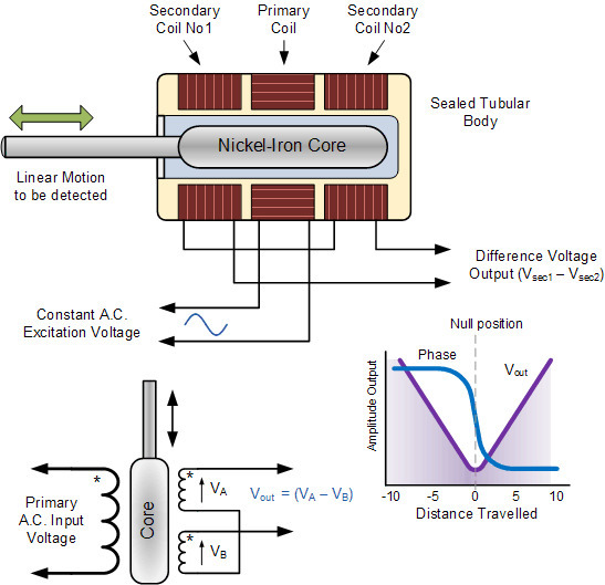
Figure 1 - Operation of an LVDT Inductive Position Sensor
These types of position sensors provide good accuracy, resolution, have high sensitivity, and offer good linearity across the sensing range. They are also frictionless and can be sealed for use in conditions where there might be exposure to the elements.
While LVDTs function to track linear movement, an equivalent device called an RVDT (for Rotary Voltage Differential Transformer) can provide tracking of the rotational position of an object. The RVDT functions identically to the LVDT and varies only in the specifics of their construction.
Eddy Current-Based Position Sensors
Eddy currents are induced currents that occur in a conductive material that is in the presence of a changing magnetic field and are a result of Faraday’s law of induction. These currents flow in closed loops and in turn, result in the generation of a secondary magnetic field.
If a coil is energized by ay an alternating current to generate a primary magnetic field, the presence of a conductive material brought near the coil can be sensed due to the interaction of the secondary field generated by the Eddy currents, which impacts the impedance of the coil. So, the change in the coil impedance can be used to establish the distance of an object from the coil.
Eddy current position sensors work with electrically conductive objects. Most Eddy current sensors function as proximity sensors, designed to establish that an object has approached the sensor location. They are limited as position sensors because they are omnidirectional, meaning that they can establish the relative distance of the object from the sensor but not the direction of the object relative to the sensor.
Capacitive Position Sensors
Capacitive position sensors rely on detecting a change in capacitance value to establish the position of the object being measured. Capacitors consist of two plates separated from each other with a dielectric material between the plates. There are two general methods that are used to detect the position of an object using a capacitive position sensor:
- By altering the dielectric constant of the capacitor
- By altering the overlapping area of the capacitor plates
In the first case, the object being measured is attached to the dielectric material, whose position relative to the capacitor plates changes as the object moves. As the dielectric material is shifted, the effective dielectric constant of the capacitor changes being the resultant of a partial area of dielectric material and the balance being the dielectric constant of air. This approach provides a linear variation in the capacitance value with respect to the object’s relative position.
In the second case, instead of attaching the object to the dielectric material, it is connected to one of the capacitor plates. Therefore, as the object moves its position, the overlapping area of the capacitor plates changes, which again changes the capacitance value.
The principle of varying capacitance to measure an object’s position can be applied to motion in both linear and angular directions.
Magnetostrictive Position Sensors
Ferromagnetic materials such as iron, nickel, and cobalt exhibit a property known as magnetorestriction, which means that the material will change its size or shape when in the presence of an applied magnetic field. A magnetorestrictive position sensor takes advantage of this principle to establish an object’s position.
A moveable position magnet is attached to the object being measured. A waveguide, which consists of a wire through which a current pulse is transmitted, is connected to a sensor that is located at the end of the waveguide. The position magnet generates an axial magnetic field, one whose field lines are coplanar with respect to the magnetorestrictive wire and waveguide. When a current pulse is sent down the waveguide, a magnetic field is created in the wire that interacts with the axial magnetic field of the permanent magnet (position magnet). The result of the field interaction is a twisting that is known as the Wiedemann effect. This twisting causes a strain in the wire which generates a sonic pulse that travels along the waveguide and is detected by the sensor at the end of the waveguide. By measuring the elapsed time between the initiation of the current pulse and the detection of the sonic pulse, the magnetorestrictive position sensor can establish the relative location of the position magnet.
Because the sonic wave will travel from the location where the position magnet is located in two directions (both towards the pickup sensor and away from it), a dampening device is located at the opposite end of the waveguide to absorb the pulse traveling away from the sensor so that its does not cause an interfering signal to be reflected back towards the pickup sensor. Figure 2 below provides an illustration of the operating principle for a magnetorestrictive position sensor.
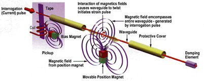
Figure 2 - Magnetoresistive position sensor operation.
By their nature, magnetorestrictive position sensors are used to detect linear position. They can be equipped with multiple position magnets to provide positional information on multiple components along the same axis. They are non-contact sensors and since the waveguide is typically housed in a stainless steel or aluminum tube, these sensors can be used in applications where they can be a potential for contamination. In addition, magnetorestrictive position sensors can function even if there is a barrier between the waveguide and the position magnet provided that the barrier is made of a non-magnetic material.
The sensors are available with a variety of outputs, including DC voltage, current, PWM signal, and start-stop digital pulses.
Hall Effect-Based Magnetic Position Sensors
The Hall effect states that when a thin flat electrical conductor has a current flowing through it and is placed in a magnetic field, the magnetic field impacts the charge carriers, forcing them to accumulate on one side of the conductor relative to the other, to balance the interference of the magnetic field. This unequal distribution of electrical charges results in the creation of a potential difference between the two sides of the conductor, known as a Hall voltage. This electrical potential occurs in a direction that is transverse to the direction of the flow of the electrical current and to the direction of the magnetic field. If the current in the conductor is held to a constant value, the magnitude of the Hall voltage will directly reflect the strength of the magnetic field.
In a Hall effect position sensor, the object being measured for its position is connected to a magnet that is housed in the sensor shaft. As the object moves, the position of the magnet changes relative to the Hall element in the sensor. This movement of position then changes the strength of the magnetic field that is applied to the Hall element which in turn gets reflected as a change to the measured Hall voltage. In this manner, the measured Hall voltage becomes an indicator of the object’s position.
Fiber-Optic Position Sensors
Fiber-optic position sensors use an optical fiber with a set of photodetectors located at each end of the fiber. A light source is attached to the object whose motion is being observed. Light energy that is directed into the fluorescent fiber at the position of the object gets reflected in the fiber and is sent to either end of the fiber where it is detected by the photodetectors. The logarithm of the ratio of the measured optical power as observed at the two photodetectors will be a linear function of the distance of the object from the end of the fiber, and therefore this value can be used to provide positional information on the object.
Optical Position Sensors
Optical position sensors operate using one of two principles. In the first type, light is transmitted from an emitter and sent over to a receiver at the other end of the sensor. In the second type, the emitted light signal is reflected from the object being monitored returned towards the light source. A change in the light characteristics (e.g. wavelength, intensity, phase, polarization) is used to establish information about the object’s position. These types of sensors fall into three categories:
- Transmissive optical encoders
- Reflective optical encoders
- Interferential optical encoders
Encoder-based optical position sensors are available for both linear and rotational movement.
Ultrasonic Position Sensors
Similar to optical position sensors, ultrasonic position sensors emit a high-frequency sound wave generated typically from a piezoelectric crystal transducer. The ultrasonic waves generated from the transducer are reflected from the object being measured, or target, back to the transducer where an output signal is generated. Ultrasonic sensors can function to perform as proximity sensors, where they report on an object being within a specified range of the sensor, or as a position sensor which provides ranging information. The advantages of ultrasonic position sensors are that they can work with target objects of different materials and surface characteristics, and can detect small objects over larger distancer than other types of position sensors. They are also resistant to vibration, ambient noise, EMI, and infrared radiation.
Position Sensor Specifications
The specific parameters that define the performance of a position sensor will vary according to the sensor type being selected since the underlying technology principles change from type-to-type. Some key specifications to be aware that apply to most position sensors are as follows:
- Measurement range – provides an indication of the distance range from the sensor for which a measured value can be obtained.
- Resolution – defines the value of the smallest position increment that the sensor can measure.
- Accuracy – a measure of the degree to which the measured position agrees with the actual position of the object being measured.
- Repeatability – reflects the range of values obtained for the measured position when the sensor performs an identical measurement over time.
- Linearity – the extent of deviation from linear behavior of the output signal measured over the range of output for the sensor.
Other selection considerations for position sensors include:
- The size and weight of the sensor
- Whether the sensor provides absolute or incremental position information
- The operating temperature range for the device
- The sensor’s ability to withstand other environmental and operating conditions, such as the presence of condensation, contamination, or mechanical shock and vibration
- The ease of installation
- The initial cost
Examples of Position Sensor Applications
Position sensors have numerous applications and are at the heart of many automated processes. A familiar one is the automated car wash. Position sensors are used to gauge where the vehicle is located as it makes its way through the car wash. This allows the cleaning equipment to be activated at the correct time. For the car wash to clean tires, it needs to know where they are and when they are in the correct position to apply cleaners or tire protectants. Give the fact that cars come in all different sizes, position sensors are needed to detect when to start and stop the cleaning process so that the car wash can adapt to different vehicles and still be effective at cleaning all of them.
Position sensors are also used to control equipment. Inductive sensors that are large loops of wire embedded in roads are used to detect the presence of vehicles in a left turn lane, to allow the traffic control system to activate a traffic light. Parking lots that have access control systems use position sensors to raise gates when vehicles approach them. Elevators use position sensors to detect that the elevator has been properly positioned correctly at a particular floor and that the elevator doors are safe to open.
Industrial processes in automated production lines use position sensors to make sure that products are properly positioned before an automatic process step takes place, such as spraying paint on an auto body, or adding water to a water bottle. Medical facilities have MRI scanners that make use of position sensors to make certain that the patient’s placement is correct before scanning or imaging begins, and to move the patient through the MRI machine.
Automotive designers and engineers use position sensors to measure important engine parameters, such as crankshaft position and throttle position .
Security cameras that have scan and tilt capability will use position sensors to establish the relative direction for the camera to assure that it is correctly oriented for the optimum view.
posted by Nikhil arutla @ November 28, 2020
0 Comments
![]()

0 Comments:
Post a Comment
Subscribe to Post Comments [Atom]
<< Home